View, Annotate and edit PDF document with notes, markup tools, text editing, find, translation and side-by-side compare
Download
ScopeLink
View live camera streams from your Android device, capture snapshots and timelapse videos and manage recordings over WiFi or USB (ADB).
Download
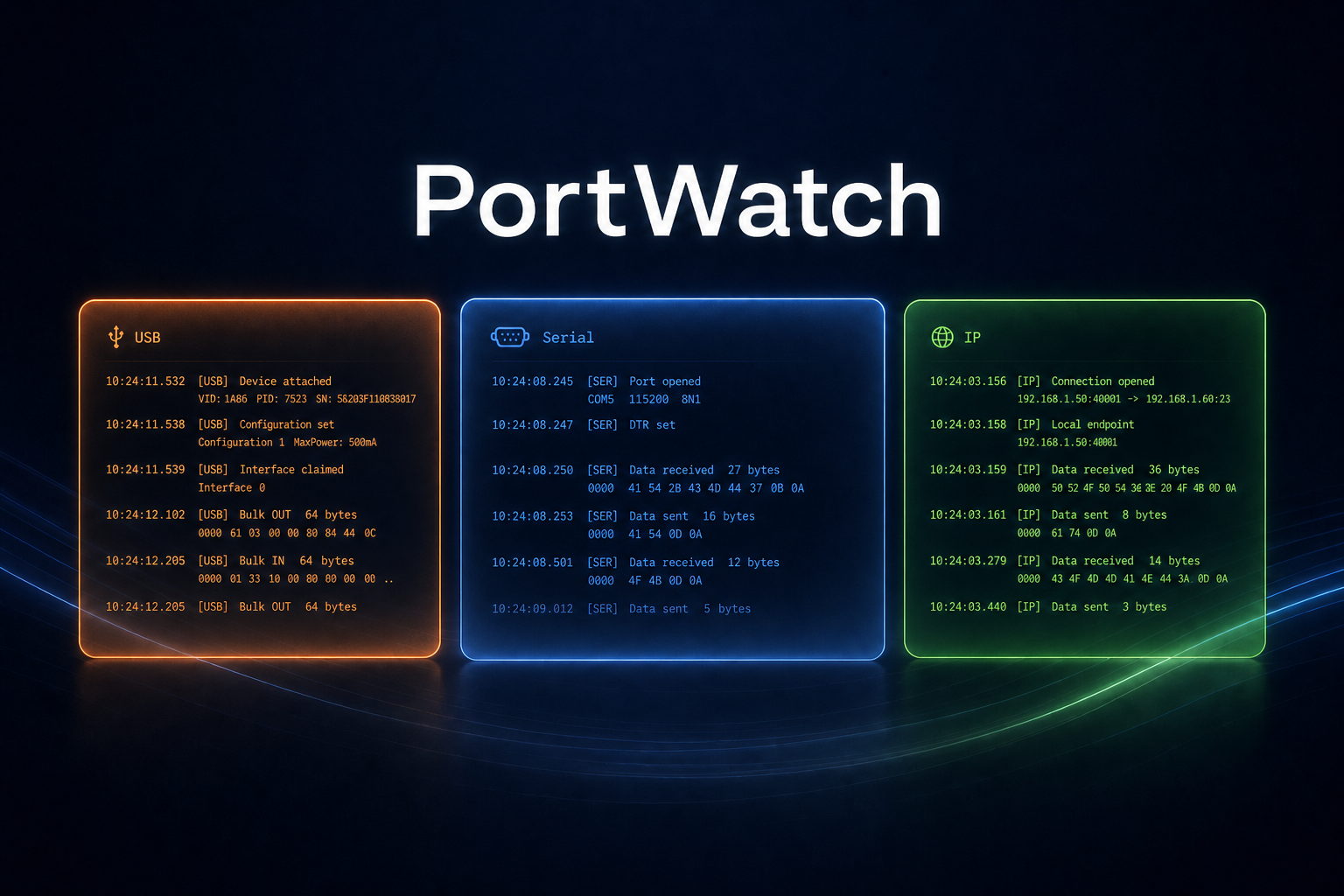
PortWatch
A debug tool for development in a Windows environment with many useful features. Connect to serial ports, USB devices and IP targets. Read logs, send/receive commands etc.
Download
Calculator
Formulas prepared for common calculations used in electronics development.